Openoffice Draw Templates Floor Plan
This is Chapter 8 of the OpenOffice.org 3 Describe Guide, produced past the OOoAuthors group. A PDF of this chapter is available from this wiki page.
Contents
- 1 Positioning objects with zoom
- 1.1 Zoom adjustments using the status bar
- ane.2 The Zoom toolbar
- 2 Positioning objects with snap functions
- ii.i Snap to grid
- 2.i.1 Showing the grid
- 2.1.2 Changing the color of the filigree points
- 2.1.iii Configuring the grid
- 2.two Snap to Snap objects (snap lines and snap points)
- ii.2.1 Inserting a snap line with the mouse
- 2.two.ii Inserting snap points and snap lines using coordinates
- 2.2.3 Editing snap points and snap lines
- 2.three Snap to folio edge
- 2.4 Snap to object border
- 2.5 Snap to object points
- 2.6 Help to position objects with guiding lines
- ii.i Snap to grid
- 3 Cartoon to scale
- iv Splitting drawings on multiple layers
- four.1 An case drawing: business firm programme and piece of furniture
- four.2 Irresolute the layer of a drawing object
- five Creating a multi-folio document
- 5.1 Using the Pages area
- 5.2 Using page backgrounds
- 5.ii.1 Creating a page background
- 5.2.two Assigning and managing page backgrounds
- half-dozen Color palette: adding or changing single colors
- 7 Irresolute colors using the Color dialog
- 8 Creating cool effects
- 8.1 Duplication
- 8.ii Cross-fading
- eight.2.one Which object goes in front?
Positioning objects with zoom
With zoom you can identify objects with higher precision.

![]()
Using zoom to identify objects with greater precision
Zoom adjustments using the status bar
The electric current zoom value is shown at the right-mitt end of the status bar next to the zoom slider.
![]()
![]()
Zoom level on Status Bar
You can adjust the zoom value by using the slider, right-click on the zoom percent to select from a carte du jour of preset values, or double-click to open up the Zoom & View Layout dialog.
![]()
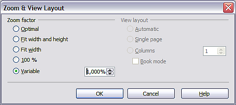
Zoom & View Layout
You lot can enter a zoom gene in the Variable field, select 100%, or use ane of the three other choices. (The three options on the right hand side of the dialog are not available in Draw; they are agile but for text documents.)
- Optimal: The drawing or selected object(not the page) is enlarged to just fit in the Draw folio area.
- Fit width and tiptop: The drawing page edges are set to the edges of the Draw page expanse.
- Fit width: The right and left page edges are set to the vertical edges of the Draw page area.
The exact result of choosing one of these options depends on whether you take the Page pane switched on or off.
![]()
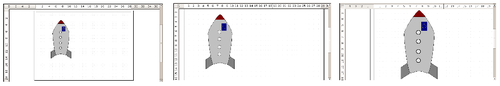
Zoom values — Fit width and height, Fit width, and Optimal
The Zoom toolbar
The Zoom toolbar provides additional zoom options. On the Standard toolbar (View > Toolbars > Standard), click on the downwards arrow of the Zoom push ![]() . Y'all can also permanently display the toolbar by clicking on View > Toolbars > Zoom.
. Y'all can also permanently display the toolbar by clicking on View > Toolbars > Zoom.
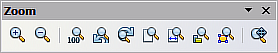
![]()
Zoom Toolbar
| | Zoom in. Enlarges the monitor picture. Get-go click on the button, and then on the object. Alternatively drag to create a zoom "window". |
| | Zoom out. Makes the monitor picture smaller. Just click on the button. |
| | Reverts objects to their original size. |
| | Changes brandish to the previous and next zoom factors. If these buttons are not visible, turn them on by clicking on the small black arrow on the championship bar of the Zoom toolbar, then on Visible Buttons and finally on either of these two buttons. |
| | Shows the unabridged folio. |
| | Zooms to page width. |
| | Resizes the display to include all objects on the slide. |
| | Zooms the selected object to Optimal. |
| | Enables moving the cartoon inside the Draw window, using the mouse. |
Positioning objects with snap functions
In Draw, objects tin be accurately and consistently positioned using grid points, special snap points and lines, object frames, individual points on objects, or page edges. This function is known equally Snap.
To apply the snap part easily, work with the highest practical zoom value. You lot can use two different snap functions at the same time, for instance snapping to a guide line and to the page edge. It is all-time, even so, to activate just those functions that you really need.
Examples for setting upwards the snap functions are establish in Advanced Draw Techniques.
Snap to grid
Use this office to move an object exactly to a grid indicate. This function can be switched on and off with View > Grid > Snap to Filigree and on the Options toolbar with the icon ![]() .
.
![]()
Verbal positioning with the snap to grid office
Showing the filigree
To make the grid visible, choose View > Grid > Display Grid. Alternatively turn the grid on (or off) with the icon ![]() on the Options toolbar.
on the Options toolbar.
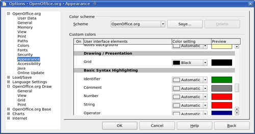
Changing the color of the grid points
By default the grid points are bright grey and non always easy to run into. Get to Tools > Options > OpenOffice.org > Advent. In the Drawing / Presentation department, you can change the color of the grid points. On the Colour Settings pulldown menu select a more suitable/visible color, for instance black.
![]()
Irresolute the colour of the grid points
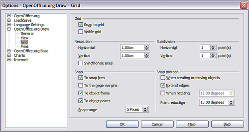
Configuring the grid
Under Tools > Options > OpenOffice.org Draw > Grid you can change the settings of the grid.
No adjustment is necessary in the Grid field, every bit these settings can exist inverse directly from the icons on the Options toolbar.
![]()
Configuring the filigree
Resolution: sets the horizontal and vertical altitude between two grid points.
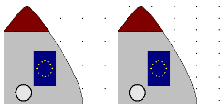
![]()
Grids with different resolutions
Subdivisions: determines how many steps there are between adjacent grid points. Intermediate steps make information technology possible to take a larger separation between two grid points, then the cartoon remains clearer. Objects tin can snap to intermediate points in exactly the same manner as to grid points.
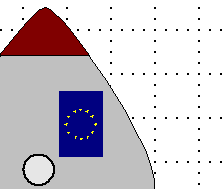
![]()
Grid with intermediate steps (subdivisions)
The snap field settings are largely self-explanatory. Ane important setting is the Snap range. Filigree points and snap lines are both visual aid elements that are managed separately by Describe. If y'all have activated a snap function and so move an object, Describe looks in the vicinity of the position of the object for those special assistance elements to determine the final position of the object; with the snap range setting, y'all can make up one's mind the extent of this search surface area. Exactly how big the snap area is depends on the electric current surround: which detail snap functions are in use, how the filigree is configured, and whether or not in that location may be collisions with other objects. It is ordinarily necessary to exercise a little experimenting to find what all-time suits your needs.
Snap to Snap objects (snap lines and snap points)
Unlike filigree points, Snap lines and Snap points are created by the user. Snap lines run horizontally or vertically and appear equally dashed lines. Snap points appear every bit small crosses, over again with dashed lines.
| | In OOo the names of the buttons in the Options toolbar are Display Guides and Snap to Guides when what is really meant is Brandish Snap line and Snap to Snap line. These will hopefully be corrected in a subsequent version. |
If y'all have activated this function, you can position objects exactly. Horizontal and vertical snap lines can be used together. Snap lines are not agile immediately after inserting them but are turned on (or off) using the ![]() icon or with the View menu. If the snap line is no longer needed you lot can hide it (or subsequently display it again) with the Display Guides icon
icon or with the View menu. If the snap line is no longer needed you lot can hide it (or subsequently display it again) with the Display Guides icon ![]() or using the View menu.
or using the View menu.
![]()
Objects 'continued' to snap lines (left) or to a snap point (correct). Note that the snap point functions as if it were the intersection of two snap lines.
Inserting a snap line with the mouse
To insert a snap line in a drawing:
- Hover the mouse cursor over either ruler (the vertical ruler to create a horizontal snap line and vice versa).
- Click and concord the right mouse button.
- Drag the mouse into the drawing area to produce a snap line.
The snap line tin can be moved at whatsoever time by dragging it with the mouse. Moving a snap line will not, yet, move whatsoever objects that have already been snapped to that line.
Inserting snap points and snap lines using coordinates
The command Insert > Snap indicate / line opens a dialog where you lot can specify X and Y coordinates and cull the blazon of snap object: betoken, vertical line, or horizontal line.
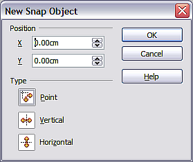
![]()
Setting a) snap object type and b) snap object position using 10,Y coordinates
Editing snap points and snap lines
All snap objects can be edited after setting them. If you right-click on a snap object, an appropriate menu opens allowing you to edit or delete the snap object.
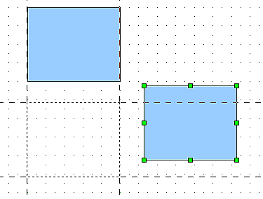
Snap to folio edge
With this function you can snap objects to the page border. A combination with snap lines and snap to grid is also possible.
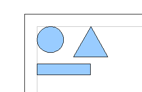
![]()
Objects positioned on the page margins
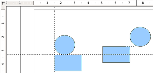
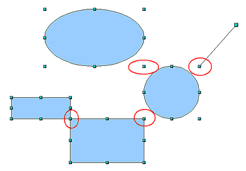
Snap to object border
With this function you can position ane drawing object on the border of another. The connection indicate can lie anywhere on the object border. To use this role, beginning conciliate Snap to grid. Figure xiv shows some examples. Note that a typical object edge will touch on the edge of a round object at but one of its four points.
![]()
Objects positioned on the edge of some other object
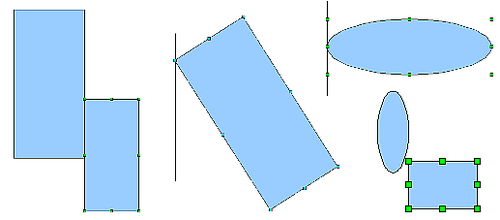
Snap to object points
This role operates in a similar manner to the i just described. The difference is that the connection point tin can lie only at 1 of the four corner points of both the object beingness moved and the target object. This leads to the situation where two round objects have a connectedness point that does not prevarication on either object but at one of the scarlet circled points.
![]()
Objects continued to the object bespeak of another object
Help to position objects with guiding lines
To simplify the positioning of objects information technology is possible to brand visible guiding lines — extensions of the edges of the object — while it is beingness moved. These guiding lines have no snap part.
The guiding lines can be (de-)activated under Tools > Options > OpenOffice.org Depict > View > Guides when moving, or past clicking the ![]() icon on the Options toolbar.
icon on the Options toolbar.
![]()
Working with guiding lines
Drawing to scale
In Draw a drawing is made on a predefined drawing area or canvas. This will usually be in the Letter or A4 format depending on your locale settings, and will be output to some "standard" printer that you have fix on your computer (commonly referred to equally the default printer). Depending on the actual size of the fatigued objects, it is often necessary or convenient to reduce or enlarge the drawing by some scaling value. Y'all tin specify the scale that y'all wish to use under Tools > Options > OpenOffice.org Draw > Full general.
The scale and selected unit are automatically reflected in the rulers, the window position and the window size. Scale settings can be stored permanently in a template that you can and then employ for new drawings.
The scale you use has no effect on the basic drawing operations. Draw will automatically calculate the necessary values (for example, dimension lines). The grid spacing is independent of cartoon scale equally the filigree is not a cartoon chemical element simply but an optical drawing assist.
| | If y'all want to insert elements in a cartoon from the Gallery or Clipboard, yous should draw these to the same calibration as you are using for the cartoon to ensure the proper size ratio is maintained. |
Splitting drawings on multiple layers
Layers are like transparencies that lie i on top of some other on an overhead projector. You tin can insert and extract single layers as desired. For case in architecture the flooring programme, heating, and electrical wiring can all exist on separate layers. With circuitous drawings this layer technique offers many advantages. Yous tin can make layers visible or invisible equally needed or you can protect a layer from further changes while you lot work.
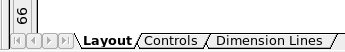
In Draw three layers are ever nowadays by default: Layout, Controls, and Dimension Lines. Layout is the default layer when you create a new cartoon.
![]()
To change to a layer, click on its tab. Everything that is drawn volition be placed on the currently selected layer. The Controls layer is for control elements such as icons and pulldowns and is not normally used for ordinary drawing elements. The Dimension Lines layer is used whenever you insert a dimension line on a drawing (unless the layer is made invisible). Use Insert > Layer to insert a new layer in a drawing (Figure 17 left).
On the Insert Layer dialog you can specify the post-obit backdrop:
- Visible: If this property is not activated, the layer will non be shown (the layer is removed from the stack).
- Printable: If this holding is non activated, the layer will not exist printed. This is useful if you utilise a "draft" layer for guides or annotations that you utilize in making the drawing but should not appear in the final output.
- Locked: All objects on this layer are protected from deletion, editing, or moving. No additional objects tin can exist added to a protected layer. This holding is useful when a base program is to exist protected while adding a new layer with other details.
Right-click on a layer tab to bring upward a bill of fare where you tin insert or delete a layer, rename an existing layer, or modify a layer. You can change the names of the user-defined layers; the default layer names cannot be changed.
If you cull Modify you will see the dialog on the correct. On the Modify Layer dialog you cannot edit the Proper noun but you can edit the Championship and Description and alter the properties of the layer (Visible, Printable, Locked).
| | Somewhat confusing is the fact that you tin can movement objects on ane layer although you are working on another layer. To avert accidentally deleting or moving objects on another layer, you should lock that layer. |
An instance cartoon: house program and article of furniture
A popular application for programs similar Depict is the "moving the furniture" scenario. Y'all tin hands depict the floor plan of a room or a business firm using Draw. The simplest way is to draw walls as thick lines. You can also draw single rectangles or polygons, place them together, select them and then from the right-click menu apply Shapes > Merge to make a single effigy, then add a hatching pattern. Before yous practise this, you should read the section Drawing to scale.
For this case a suitable measurement unit is centimeter. The cartoon scale and filigree settings depend on the size of the floor program.
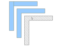
Apply the Position and Size dialog (right-click and cull Position and Size) to easily position and dimension the private wall sections. Make sure that the rectangles completely overlap, otherwise the merging will give uneven edges.
![]()
Wall corner from 2 rectangles. From upper to lower: before merging, after merging and after hatching
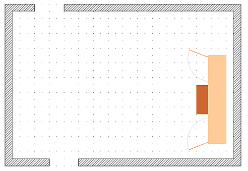
The side by side figure shows the finished floor program. In improver, a chest of drawers has been added.
The body of the chest is drawn on the Layout layer; the pulled-out drawer and the open doors are fatigued as a group and put on a separate user-defined layer (Layer4 in our example).
![]()
Floorplan with chest of drawers
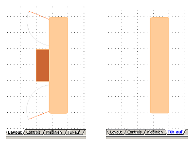
Here is how this is washed. Making the layer with the drawers and doors visible or hidden volition show them open up and closed. Hidden layers are shown with a colored tab.
![]()
Using layers for unlike parts of a drawing. (Left) Describe the body of the chest on the Layout layer. (Right) Create a new layer and draw the open drawers and doors, keeping the Layout layer visible to help y'all position the additional objects.
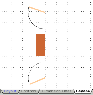
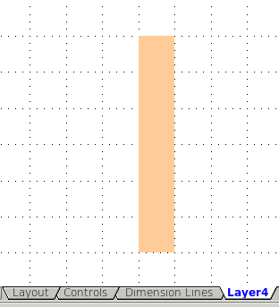
| | | ||||||||
Making layers visible or hidden. (Left) Hibernate the Layout layer to meet what is on Layer4. (Right) Evidence the Layout layer and hibernate Layer4 to show chest with drawers airtight.]]
Irresolute the layer of a drawing objectDraw has no direct command to change layers. To motion an object to some other layer, alter to the new layer, select the desired object or group, so cut and paste information technology into position. Watch the status bar (the selected object's layer proper noun is shown in the information field) to follow and check the modify. You tin can besides click on the object, hold the mouse button pressed for nearly two seconds until the mouse cursor changes from a hand to a arrow with an open rectangle, and then drag and drop it on the appropriate layer. Creating a multi-page documentDepict documents, like presentation (Print) documents, tin consist of multiple pages. As in Impress, tools to manage pages and backgrounds are bachelor. Pages are automatically named as Slide one, Slide two, and so on. This description is relative; if yous move pages around, they are automatically renumbered. If you want to accept fixed slide (page) names, you must proper name them yourself. Page names are useful for working with the Navigator and when y'all want to insert single slides using Insert > File into some other certificate. Using the Pages expanseUsing page backgroundsWith background pages y'all gear up common page settings for multiple pages of the Draw document. These include setting the color or graphics of the background, groundwork objects, and fields such equally folio numbering and author.
Creating a page backgroundChange with View > Master to the Master view and note that a related Principal View toolbar opens. If this toolbar does not appear, activate it with View > Toolbars. In this toolbar are switches for a new background page and for renaming the master page. These functions are likewise available by correct-clicking on a page picture in the Pages area of the Master view. The push button for deleting a master page is only bachelor when y'all select a background folio in the Pages area which has not yet been assigned to whatever page. Master View toolbar To return to normal mode, click the Shut Main View push button or View > Normal. Yous can edit background pages merely similar normal pages. With Format > Page > Background you can set the colour, pattern, or background picture. These settings are specific to each background page. In the Main view, you tin set the size and orientation of the folio; such settings apply to all pages. If you insert cartoon objects on a background page, they are visible on all pages that use this background. This a convenient way, for example, to place a logo on every page. Master pages are organized in layers only like normal pages. The layers of normal pages are associated with the layer of the same name on the Main folio. Accordingly the layers Layout/Control/Dimension Lines are considered to be a unit and the Master folio layer Background objects is associated with them. With Insert > Fields you can insert the date, time, page number, author and filename. No other fields are available. With folio number you cannot insert a fixed page number but merely a variable; the actual number appears on the folio itself and is determined by the position of the page. The number is automatically adjusted if the folio is subsequently moved. Assigning and managing folio backgroundsYou tin can open the Slide Blueprint dialog in ii means:
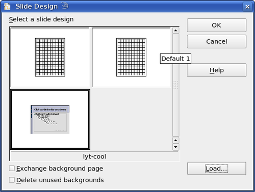
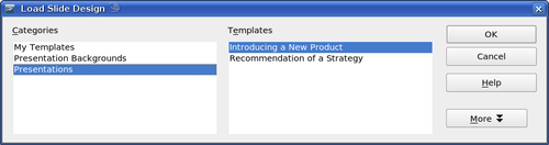
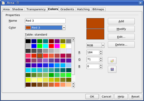
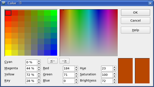
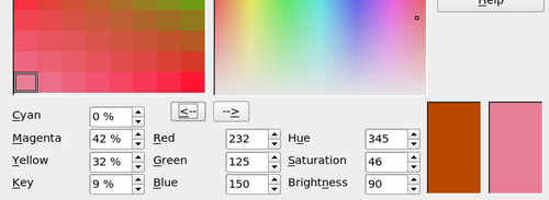
The Slide Pattern dialog shows the available background pages for that folio. Slide pattern dialog If the Substitution background folio pick is selected, the selected background page will be used on all pages of the document, not only on the currently active page. The Delete unused backgrounds option deletes any backgrounds (as shown in the Slide Pattern dialog) that have not been assigned to a folio. Click the Load button to open the Load Slide Design dialog. From here you tin can load previously prepared background pages. All Depict and Impress templates tin be used for this purpose. Notation, however, that using Impress templates will bring in only the background and not the other elements prepared in Print. Load Slide Blueprint dialog There is no special option to store background pages as templates. Instead you can load a certificate with the desired background page and store this document as a certificate template with File > Template > Store. Color palette: calculation or changing unmarried colorsDraw (like all OpenOffice.org components) uses color palettes for the representation of colors. In addition yous can customize the color palette to suit your own needs and wishes. You can alter colors in a palette, add together other colors, or create new color palettes. Accomplish these options with Tools > Options > OpenOffice.org > Colors or with Format > Area > Colors (tab). The latter method allows color palettes to be loaded or to be stored for future apply. Whatsoever modifications made to colors apply but to the currently agile palette. The Colors tab in the Area dialog OpenOffice.org ever uses the RGB color model internally. Other methods are also available for the definition of a color value. The colour values can be input directly as numbers. Choose betwixt the RGB color model (base colors Red, Green and Blue) and CMYK (base colors Cyan, Magenta, Yellow and Blackness, Yard= Primal). The conversion to RGB values is made automatically. Individual color tones are produced by using different values of the base colors. The color value tin can exist any integer value between 0 and 255. As an example, Carmine 3 has a ruddy value of 184, a green value of 71 and a blue value of 0 in the RGB model. The CMYK color model uses percentages (in this case 0%, 44%, 72%, and 28% respectively). Modify these values to manipulate the color tone. Either enter a number directly or use the spinners on the correct side of each field. The change in color will exist shown in the lower color field. Click the Modify button to utilize and store the new setting. To add a new color to the current palette, enter a new proper name in the Name field and gear up the desired colour values. Click Add. The new color volition be added to the finish of the palette and stored in the currently agile palette. Yous can also delete colors from a palette. Select the colour from the Color pulldown menu and click on the Delete button, then on OK to confirm the change. Click on the Edit button to open a dialog where y'all tin gear up private colors. Many more than input possibilities are bachelor in this dialog. In the lower area you tin can enter values in the RGB and CMYK models as well as the HSB (Hue, Saturation and Brightness) model. The two colour samples at the lower correct show the electric current color (left) and the new color specified by the color value fields (right). Color dialog The color windows in the upper area permit a direct selection of colour without any knowledge of color values. The right upper colour window is linked directly with the diverse colour model input fields; if you lot click on a color in this window the numbers alter appropriately and a preview of the color appears in the correct of the two color fields (lower right in the figure; see also Method 2 below). If you click OK, the color window is closed and the input field is again active. You lot can at this stage select the colour you have merely defined, requite information technology a new name, and shop it by clicking the Add button. The onetime color volition then (without any farther warning) be overwritten. Changing colors using the Color dialogMethod 1 You tin change the current color past modifying the individual color values explicitly. Information technology is possible to modify from one color model to another during this process simply the settings are always calculated and stored according to the RGB model. This may consequence in some slight adjustment to your input values in the other models.
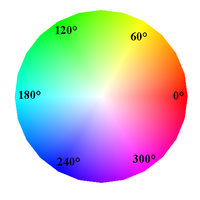
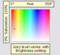
Method 2 You can select a new color past clicking on a point in the color window at the upper right of the dialog. The chosen color is shown in a black frame which tin be dragged with the mouse. If this color is not quite right, yous tin fine tune it as described above in Method 1 past changing the color values.
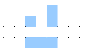
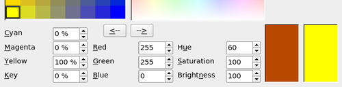
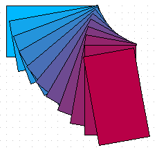
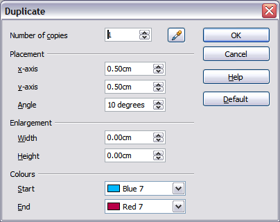
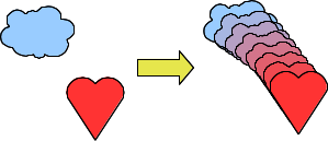
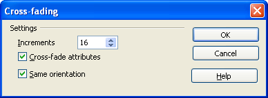
Method three The left colour window is divided like a chess board into eight x 8 individual fields, each with a dissimilar color. Most important are the colors in each of the corner fields. The colour red changes stepwise to light-green in the first row, and stepwise to yellowish in the offset column. The color green in the last cavalcade changes stepwise to bluish. This window thus contains a stepwise change between each of the iv main colors in the corner points. If you hover the mouse over a foursquare the RGB value is shown every bit a tooltip. For example, the yellowish corner field (lower left) has RGB values of 255, 255 and 0 (full red, total dark-green and no blue). Click on this yellow field. A frame appears. If yous click the -> arrow nether the color windows the selected color is assigned. Y'all can modify the colour spread in this window to a more specific range by changing one or more of the corner fields. Click on the corner you want to change, so select the preferred colour from the right color window with the mouse and/or set information technology using the number fields. At present click on the <- pointer; the new color will be assigned to the corner square you lot selected and the overall advent of the window changes accordingly. Changing the colour of a corner square Creating absurd effectsDuplicationDuplication makes copies of an object while applying a set of changes (such as color or rotation) to the duplicates. Duplication example To start duplication, click on an object or group and cull Edit > Duplicate. The Duplicate dialog appears. Duplicate dialog Choose the number of copies, their separation (placement), rotation, and and then on. The choices above applied to a bluish rectangle produce the result shown above. Cross-fadingCross-fading transforms i shape into another. The result is a new grouping of objects including the ii finish points and the intermediate steps. Cross-fading example To exercise a cross-fade, showtime select 2 objects. The two objects selected for cross fading Then choose Edit > Cross-fading. Cross-fading dialog On the dialog choose the number of increments (transition steps). You probably desire to have Cantankerous-fade attributes and Aforementioned orientation both checked. The end result is shown at the beginning of this paragraph. Which object goes in front?How practice I tell Draw that I want Select | |||||||||

Source: https://wiki.openoffice.org/wiki/Documentation/OOo3_User_Guides/Draw_Guide/Tips_and_Tricks
Post a Comment for "Openoffice Draw Templates Floor Plan"